MTOR Ray Tracing OverviewMTOR Ray Tracing Overview
The majority of ray tracing effects possible in PRMan are accessible to the RenderMan artist via MTOR and Slim. These effects range from traced reflections, to refractions, to subsurface scattering, to indirect illumination. They can be much more expensive than the traditional bag of cheats, but they may often provide the only solution. Knowing when to use ray tracing (or perhaps more appropriately, when not to use it) is key. Here we'll outline the various ways that rays may behave.
In PRMan the reyes algorithm and ray tracing live side by side in a hybrid rendering scheme. The addition of ray tracing to PRMan does not limit its fundamental performance as a scanline renderer. However, when ray tracing is desired, surface shaders can be created that know how to perform any number of trace requests. These shaders then probe the scene with rays.
To make ray tracing more feasible in production environments, the management of ray tracing calculations has been given careful thought. First, only surfaces who need to cast rays are required to perform ray tracing calculations, so you can pay for ray tracing only when needed. Secondly, there is a high level of control over how rays are cast from these surfaces. Rays can be restricted by distance, so that rays only travel a finite length, avoiding unnecessary calculations. Rays emitted from one surface can be told to only trace a select group of objects, which can be useful for special effects and/or to increase efficiency by reducing ray run time. Using these various techniques to limit the amount of ray tracing in a scene can have a substantial impact on making tracing as efficient as possible in a production environment.
These documents provide the introductory footing needed to get acquainted with ray tracing in PRMan, from reflections, to caustics, to irradiance caches.
How do I enable Ray Tracing?
Ray tracing must be enabled in the RenderMan Globals. If disabled all ray trace
requests are ignored. That is controlled with the Enable Ray Tracing
parameter.
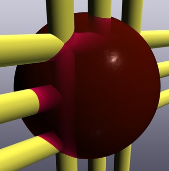
How can I make cool glass?
Use the Slim Glass
shader. Attach it to an object. If it has volume, enable the "double
sided" parameter. Render. Tweak. Repeat.
| Trace Settings All of the primary controls for ray tracing operations are found in the RenderMan Controls, in the Rays tab. This panel is divided into two halves. The top half of the panel contains knobs for all tracing options, from enabling ray tracing to global quality controls. The lower half is divided in three parts: general attributes, the irradiance cache, and photon mapping. |
|
| The RenderMan Globals Rays
Panel
Enable Ray Tracing - Global control for enabling and disabling
ray tracing. This causes MTOR to tag each object with visibility
attributes required by PRMan's ray tracing subsystem. Only objects made
visible to this subsystem will appear in ray traced reflections and
shadows. |
|
| General Attributes Sub-Tab This panel controls general ray tracing attributes. Values provided here act as scene-wide defaults and these can be overridden on a per-object basis. Here you can set the ray bias, limit the specular and diffuse ray depth and establish traced displacement policy. Max Specular Depth - Limits the number of specular bounces
(reflections and refractions) for ray traced from the associated
primitive. To resolve the interaction between per-primitive values, we
pass the current max down the ray tree and apply MIN(ray.depthMax,
primitive.depthMax + ray.depth). You can use this attribute to limit the
number of reflection and refraction bounces and thereby tune your
rendering speed. A value of 1 is necessary to get any reflections. A value
of 2 is required for refractions through solid objects. Higher values are
required for inter-reflecting surfaces. A value of 1 or 2 is a reasonable default.
(For photon map computations, values higher values, such as 5, as
recommended.) This value acts as the scene default and you can
override this value on a per-primitive basis via the Slim Ensemble. |
|
Ensemble Overrides
Many of the settings found in the Rays Control Panel can be overridden on a per
shader basis, via the controls found in the ensemble. These controls allow you
to assign ray tracing behavior on a per-surface basis, overriding the scenes
defaults and independent of other surfaces.
The ensemble's ray controls default to the global settings defined in MTOR's Rays Control panel. By explicitly setting values for these parameters the ensemble will override the global settings. This explicit control on a per-shader basis allows shaders to be configured to only perform as much work as needed, so if one shader requires a higher quality setting, like multiple ray bounces, other shaders can still use lower quality settings. In this way scenes can be managed to do only as much tracing as needed. For more information about the ensemble ray overrides refer to: The Ensemble's Ray Tracing Controls
Any shader can make a ray trace request, and PRMan affords a lot of flexibility in what a shader may ask a ray to do. Rays can be sent off in arbitrary directions, along the reflection direction, along the normal, along the refraction direction, etc. Rays can be blurred and multi-sampled. Rays can be jittered around a surface point or shot from any arbitrary point in the scene. A ray can return color, surface opacity, distance, or any arbitrary attribute. Rays may also be "tagged" with a label, so that rays with different labels cause other shaders to behave differently.
Slim provides access to all of these operations. In some cases, like Swiss Army, Slim makes assumptions for you about the ray direction and origin, but in other cases, like the Ray Trace color, these may be adjusted on a per-shader basis for the instances when this level of control is required.
| Ray Origin Ray origin determines when a surface point is hit, where the ray will be fired from. Generally, CurrentPoint is the preferred selection. |
|
| Types of Origins Any type of manifold can be used as an origin for a ray trace call. In all but the most eccentric cases, however, you'll want to shoot rays from the current surface point, and so CurrentPoint is generally the best bet. |
|
| Ray Direction Ray direction is highly useful. This determines the difference between reflection and refraction, by the direction the ray bounces off an object. In some Slim templates assumptions are made about this, but others allow you to tweak the ray direction yourself. |
|
| Ray Direction Types A shader that makes a ray trace request can send a ray off along any of these vectors, which includes arbitrary direction. |
|
Samples By increasing
the ray samples, we increase the amount of rays cast from any point.
For some effects a sample of "1" may be sufficient. However,
other times casting multi-sample allows for greater image quality (using
multi-sampling for anti-aliasing) and special effects (like blurry
reflections). Higher samples will also dramatically add more time to
rendering and should be increased with care. By increasing
the ray samples, we increase the amount of rays cast from any point.
For some effects a sample of "1" may be sufficient. However,
other times casting multi-sample allows for greater image quality (using
multi-sampling for anti-aliasing) and special effects (like blurry
reflections). Higher samples will also dramatically add more time to
rendering and should be increased with care. |
Typical "Sample" Parameter, increase for higher fidelity and expect longer render times. |
|
Sample Base This
parameter allows rays to be jittered from any given point, as measured in
micro-polygons. The direction of the ray doesn't change, only the position
from where it is cast. This allows for a broader sampling when creating
multi-sampled anti-aliased-type effects. This
parameter allows rays to be jittered from any given point, as measured in
micro-polygons. The direction of the ray doesn't change, only the position
from where it is cast. This allows for a broader sampling when creating
multi-sampled anti-aliased-type effects. |
"Sample Base" Parameter |
|
|
In the first image on the right we have a ray tracing "window," a rectangle in the middle which rays are shot into the scene. The first image is generated with one sample. Look closely and you can see a certain amount of "jaggies" along the edges. By increasing the samples to ten, the jaggy artifacts are reduced. In this case each of the twelve rays is slightly jittered, effectively anti-aliasing the samples. |
 1 Sample
|
|
Blur Increasing the
value of blur increases size of the ray's sample cone. This allows the
creation of blurry reflections, refractions, subsurface scattering, etc.
Blurring traces also requires a greater number of samples to be cast from
any given point in order to reduce splotchy artifacts. Increasing the
value of blur increases size of the ray's sample cone. This allows the
creation of blurry reflections, refractions, subsurface scattering, etc.
Blurring traces also requires a greater number of samples to be cast from
any given point in order to reduce splotchy artifacts. |
"Blur" Parameter. Measured in Radians |
|
|
In the images on the right, the number of samples has a large effect on the quality of the resulting image. In this case, twelve samples might not be enough for a high quality render, but twelve produces a much more acceptable effect than one single sample.
|
 1 Sample "0.25" Blur |
 12 Samples "0.25" Blur |
|
Here the reflection blur has been increased to "1.0" Notice how the blur of the reflection increases as it recedes from the base of the cylinder. Again samples could be increased to a value higher than 12 for a final render.
|
 1 Sample "1.0" Blur |
 12 Samples "1.0" Blur |
Here's more technical information about multi-sampling.
| Trace Sets Trace sets provide a method to define which objects a particular shader will trace. Objects can be defined as trace sets (which are simple Maya sets with an added attribute). These sets can be referenced in shaders in the "Trace Set" parameter. The visibility of objects to tracing can still be enabled and disabled on a global level (using Maya's Attribute Spread Sheet). The Trace Set brings an added level of control where objects can be visible to tracing on a per-shader basis. The effective use of trace sets can limit the total amount of ray
tracing calculations which are performed in a scene, significantly
reducing memory requirements. |
|
|
Referencing a Trace Set To reference a trace set from a shader performing trace calculations, add its name to the "Trace Set" field. |
|
|
Creating a Trace Set To create a trace set, select all of the objects in Maya to be included in the set and pick "Create Trace Set" from the RenderMan menu. Trace sets can be managed and edited using the Maya Set Editor. |
|
|
Naming the Trace Set The trace set can be quickly named by selecting the Option Box. |
|
|
The Trace Set Attribute A Trace Set is a simple Maya set with an added attribute called "RMan Trace Set." |
|
| Example #1 | |
|
|
|
|
|
|
|
|
|
Here's more technical
information about trace sets.
Max Distance The
distance that rays travel from surfaces can be limited so that the rays
are cast a fixed distance. This allows rays to sample only objects which
are within a set proximity, saving the added cost of probing a scene,
hitting and dicing geometry, and running shaders of remote objects that
have little bearing on the effect. Max distance is especially useful when
used when indirect illumination, or other effects which require many
blurry samples when occlusion culling of nearby objects is most
important, and far away objects have less relevance. The
distance that rays travel from surfaces can be limited so that the rays
are cast a fixed distance. This allows rays to sample only objects which
are within a set proximity, saving the added cost of probing a scene,
hitting and dicing geometry, and running shaders of remote objects that
have little bearing on the effect. Max distance is especially useful when
used when indirect illumination, or other effects which require many
blurry samples when occlusion culling of nearby objects is most
important, and far away objects have less relevance.
If a ray travels the entire max distance without hitting any objects,
it expires; the ray misses. When a ray misses it returns black by default,
which is not always useful. Many shaders allow the specification of an
environment map when a ray misses, which significantly increases the
usefulness of max distance. |
|
| Setting Max Distance The control for max distance can be adjusted using the "Max Distance" parameter. Setting the value to "-1.0" causes the shader parameter to inherit the global default defined in the RenderMan Globals.. The value of Max Distance is set in world units. |
|
 Max distance = infinity The entire scene is reflected in the wall. |
|
 Max distance = 12 The rays stop shortly after reaching the third barrel |
|
 Max Distance = 4 The rays stop after reaching the first barrel |
|
 Max Distance = 4, with blue environment map The environment map is used when a ray "misses"; when it travels its max distance without hitting anything. The environment map was specified in the shader, in this case Swiss Army. |
|
 Max Distance = 4, with blue environment map and indirect illumination Here's a scene where max depth comes in handy: Some color bleeding is wanted along the bottom of the wall, only objects close to the wall will have any effect. So Max Distance is used to limit the rays to only those objects close to the wall. |
|
Here's more technical
information about Max Distance
| Traced Output Variables When a ray is cast from a surface into a scene, it can be told to return any arbitrary data about any surface it hits. Usually color is returned by default, but PRMan provides a method to return other types of data, as well. For the non-programmer, there are a few interesting alternatives to color that can be returned from a surface. However, the full potential of output variables requires custom shader and templates that have these variables built into them. This is supported by Slim's Ray
Trace Messaging function. |
|
||
| Message Spec The "Message Spec" parameter defines what info a ray cast from this surface will return. Some of the more interesting options are:
ray:length Returns the length of a ray. ray:direction Returns the direction of a ray.
surface:s Returns the S coordinates surface:t Returns the T coordinates Not all of these options are immediately useful, but they're available
as an option. Out of them all, ray length is probably the most useful.
The length of the ray can be added to shaders to create special effects. |
|
||
| Example: Mapping Ray Length The length of the ray is returned in world units. So if a ray travels 15 units, its value will be 15. Often it is useful to map these values between 0 and 1. To do this use the Remap Node. The image on the right shows which parameters to adjust. |
|
||
 Now the mirror casts rays that return ray length, not color. Closer areas are blacker. Whiter areas are farther. In this case the inputmax has been set to "20." |
|||
 The same rays cast along the normal, instead of the reflection direction. This setting can be adjusted with the Ray Direction Parameter. |
|||
 The same rays, this time cast from an arbitrary direction using the Ray Direction Parameter. |
|||
|
|||
Here's more technical information about Traced Output Variables.
| Ray Labels Ray Labels allow messages to be attached to rays that are cast from objects. These labels can contain arbitrary information. Shaders can evaluate the labels attached to rays and behave accordingly. In this way messages can be passed from a surface casting rays to the surfaces those rays hit. |
|
| The Ray Label Parameter Currently ray labels require custom shaders that know how to evaluate these messages, and this requires knowledge of shader programming. However, if you have a set of custom shaders that evaluate labels, the message can be added in the "Ray Label" field. |
|
Here's more technical information about Ray Labels
| Ray Traced Shadows Light sources can trace shadows. Traced shadows have several features that traditional shadow maps lack. Traced shadows can be used to create soft shadows, colored shadows, and motion blurred shadows. They are also independent of resolution, unlike shadow maps. (Note that Deep Shadows can be used to create many of these same effects more efficiently than traced shadows.) |
|
| Using Traced Shadows To create traced shadows, connect a "Ray Traced Shadows" function into a light shader's "Shadow" parameter. |
|
| Colored
Shadows With ray traced shadows it is possible for rays to absorb the color of semi-transparent objects, creating the effect of colored shadows. The transmission of color is automatic, but there are a couple guidelines for proper set-up: 1) You'll want to color the opacity parameter of the object. The rays absorb color from opacity, not surface color. A surface with a colorful image map but a gray opacity will produce a gray shadow. Include the color in the opacity. 2) The shadow rays actually absorb the inverse color of the opacity. So invert the opacity's color with the Invert Color function. For proper conversion the invert color function should be set to only invert the hue and not the value (which would invert the opacity). 3) Ensembles should be used with objects that cast semi-transparent shadows. The "Cast Shadows" parameter of the ensemble must be set to "Shade" to evaluate the opacity of the shader. Here's more technical
information about Transmission. |
|
| Blurred Shadows When blurred, ray traced shadows can create Soft Shadows. To create soft shadows just increase the amount of "blur." You'll also want to increase the shadow "samples" for higher quality shadows. For a final image, if you see little dots, increase the samples. Since increasing samples can add a lot of computation time, during iterative renderings keeping samples lower will speed things up. Samples Sample Base Blur Bias Trace Set
|
|
 Shadow Blur 0.25 ~ Samples 1 |
 Shadow Blur 0.25 ~ Samples 24 |
|
|
|
| Hybrid Shadows: Traced Shadow
Maps Traced shadows and shadow maps can be used in combination to create efficient hybrid shadows. The shadow map is generated during a pre-pass and then during the final pass rays are shot along the edges of shadows, in areas of high variation, to fill in any details which the shadow map lacked due to pixel resolution. Hybrid shadows work well in cases where entire scenes with many small objects are all shadowed by the same light, like the sun. The shadow map does the bulk of the work, and the traced shadow rays fill in the missing details. |
|
| Hybrid Shadows: Knobs and
Buttons To create hybrid shadows: 1) Enable shadow map generation under "Make Shadow Map" |
|
| Most of the effects of area lights
can be obtained using pseudo area lights. A pseudo area light is
a light shader that computes illumination from multiple points in an area
around the light source center position.
In general, the pseudo area light shader can distribute the light sampling points on any shape. Below is shown two examples (along with a standard point light for comparison). Slim provides the Pseudo-Area Light to create these specialized area light effects. |
|
| Creating a Pseudo-Area Light
|
Here's more technical information about Pseudo-Area Lights
Should I pay attention to surface normals?
Surface normals help determine how a ray bounces when it hits a surface. If
surface normals of an object are facing the wrong direction, reflections will
not appear correctly. Ensure that traced surfaces have outward facing normals.
|
Pixar Animation Studios
|