Shader
RecipesShader
Recipes
Shader
RecipesShader
Recipes
Advanced Ray Tracing: The Jam Shader
Creating shading networks can be as simple as plugging a fractal into a color parameter, but there are certain combinations of nodes that can only be unlocked with secret handshakes. Creating these combinations is simple enough . . . if you know how to do it, and that's what we've put together a cookbook of shading network recipes. You'll find some of these combinations are used a lot, if not all of the time, and an understanding of them is essential to building shaders that serve any purpose at all. On the other hand, some of these recipes cook up results that won't be used often but do serve to showcase different eclectic effects that can be accomplished with Slim.
Each recipe is composed of a simple assemblage of nodes, effectively small branches. These branches can be built into larger complicated shaders by using the basic ideas behind each concoction.
Projection techniques are the bread and butter of shading CG surfaces, whenever natural surface parameterization won't suffice. Projections are used everywhere from mapping textures to mixing opacity values to animating displacements, and because of that it's important to know how to incorporate a projection into your Slim shading networks.
Building a projection into a shading network is simple and routine task, once all the details are understood. Here we'll build a planar-z projection for a color image into a shading network. Slim supports the comprehensive set of projection techniques, and the techniques shown here transfer to projecting any kind of float or function using any of the projection types.
 |
|
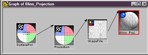
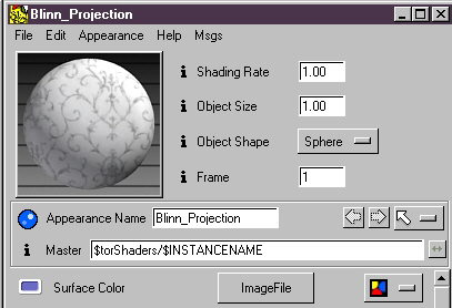
1) On the top level we have a Blinn. |
That's all it takes to create a projection. Of course, it's important to also properly configure all of the nodes creating this projection. For a more detailed view of configuring a projection, read on . . .
|
1) First off, connect an Image File to the surface color parameter of the shading model in question, in this case a Blinn. |
 |
|
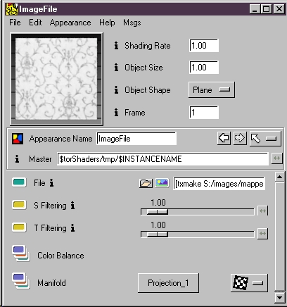
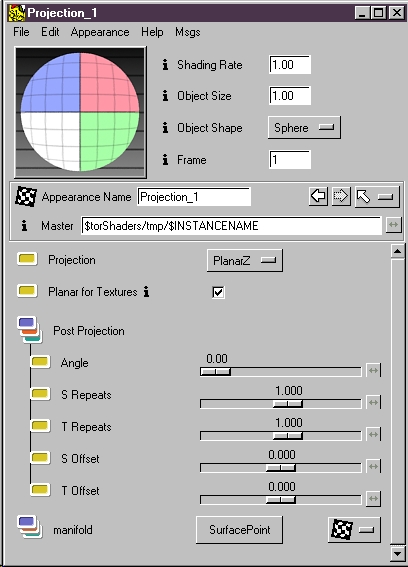
2) Select your image file (under the File folder icon). Next convert tif images to Pixar's efficient texture format. (Review using textures here.) With the image properly configured (It should render in the swatch) attach the Projection manifold at the bottom of the appearance editor (as shown). |
 |
|
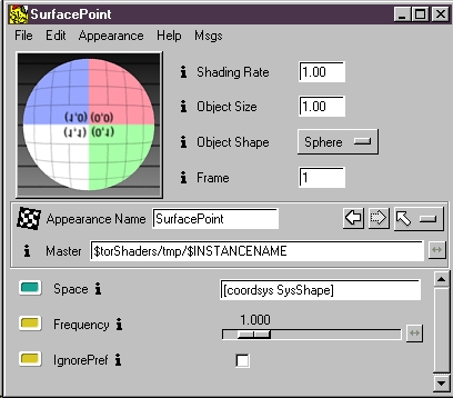
3) The Projection Manifold is where the type of projection is defined. The default projection is PlanarZ, but other projection types can be selected from the pull-down menu. With the projection properly configured, attach a Surface Point manifold (as shown). |
 |
|
4) The Surface Point Manifold is where essential information is provided to MTOR. The MTOR coordinate system shape name must be entered into the Space parameter. The projection will be cast from the position of the coordinate system. When entering the coordinate system name, use the
syntax: That's it! |
 |
Projecting Textures onto Surfaces
Tutorial: Basic Texture Projection
Lighting is a key element in most CGI imagery. Slim provides facilities for developing light shaders and for tweaking lighting effects in your scenes. Special features are available to allow you to control primary and global illumination effects.
Slim and MTOR come with a wide variety of shaders for special effects. These are described elsewhere and you should take the time to familiarize yourself with them. As a rule, if a shader already exists that provides you with the effect you need, then use it! No need to populate our overburdened world with a bunch of redundant shaders.
Lights come in a few distinct flavors. First, we can discriminate lights by the geometry of their light rays. Light that emanates from a position within your scene and whose rays diverge is said to be local. Contrast this with light that appears to be coming from an infinite distance and whose rays are strictly parallel. Such lights are called distant lights and their shadows have a distinctive quality.
We can also discriminate lights by the kind of light that they emit. Ambient light, for example, never causes specular highlights. Slim supports the notion of Environment Lights - lights which emit a special kind of light that's only visible to functions that are looking for it. The idea is to construct a system of collaborating shaders and so we wire special reflection and refraction sampling functions (like Collect Reflections) into our surface shaders. Now, when we include one or more Environment lights in our scene, they'll be detected by all surface shaders that want reflections. The power of this approach lies in the ability to control global illumination effects through a small number of controls associated with the environment lights rather than through controls associated with each surface shader in our scene. Sometimes per surface reflections are desirable and in this case we can simply access environments through Environment Maps or Reflection Maps that are wired directly into our surface shaders.
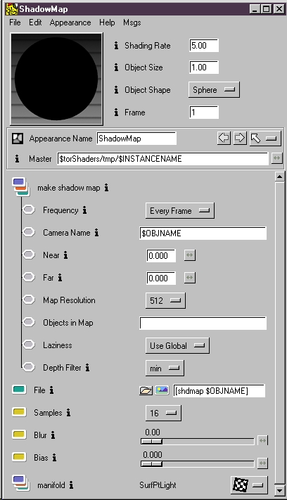
Building shadows into Shading Networks is straightforward. For spot lights and distant lights it's simply a matter of connecting a shadow map calculation to the light. You can either connect a regular shadow map or a soft shadow map to spot and distant lights. You'll find point lights have shadow map capability built right in, since they only support one type of shadow.
Here we'll show how to build a regular shadow map into a spot light.
 |
|
1) The top node is a Spot
Light. |
Here's how the Shadow map is configured:
|
To configure shadows properly two things must be done. 1) Enable shadows. This is enabled by default. "Frequency" is already set to "Every Frame". This will cause a shadow to be created for each frame of an animation. This setting can be changed to "Once per Frame" if the shadow only needs to be calculated once (for stationary geometry, for instance). 2) Reference the shadow map. To reference the shadow select "Shadow" from the Reference Texture pull-down menu (found in the "File" parameter). For more information about generating shadow maps see: Using Computed Maps. |
 |
Computed Maps: Automatic Shadows, Reflections and Environments
Tutorial: Shadows & Shadow Maps
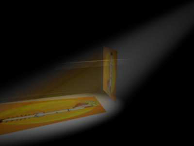
An image can be projected from a light source . . . like a slide projector casting slides onto a home movie screen. Using this technique, an arbitrary amount of objects can be colored by a single image. In the example below, an image of a street scene has been projected onto two boxes and the floor.
Here's how you can build your own slide projector shading network.
For a Spot Light:
Here's how the shading network should look in the call graph:
Directional Light modifications:
Use the same process as above with a couple changes.
Explore this example further by examining the Maya scene file, available in the tutorial scene files. You'll find it here: mtor/scenes/light_texture_projection/texture_projection_via_light.ma
Distant light is very useful in Computer Graphics because it simulates a common lighting effect, parallel light beams, like the sun. Distant lights have a global effect, illuminating the entire scene. This is fine for sunlight, but often its helpful to constrain the area that a distant light illuminates.
To that end, Slim's Distant Light provides a "Barn Door" parameter to allow you to define an illumination rectangle in a manner analogous to a spotlight's cone angle. Usually, Barn Door will illuminate a one unit square.
|
|
Important: A coordinate system may also be parented under the distant light to intuitively control the size and ratio of the Barn Door effect. Be sure to reference the shape name of the coordinate system in the distant light's Shader Space parameter.
|
|
The additional benefit of this approach relates to shadow map generation, allowing shadow maps to be placed quite accurately, including only those objects needed to cast shadows. Shadows will have a higher quality when a shadow map is tightly bound around shadow casting objects and at the same time keeping shadow maps to a minimal resolution. It's important to note that even with the Barn Door effect disabled, that a coordinate system can define a shadow map, allowing a distant light to illuminate an entire scene while generating an arbitrarily constrained shadow map. Here are a few techniques used to generate shadow maps with distant lights:
Normally, MTOR uses the bounding box of objects (those objects with shadows enabled) to calculate shadow maps. Sometimes it suffices to turn off shadows on all objects which won't be casting shadows into a scene, like floors for example.
For more precision, the Barn Door coordinate system can be used to generate a shadow map that is referenced by the distant light, using a standard map generator. Be sure to refer to the coordinate system's shadow map in the distant light. (Review technique here.)
Using an alternatively precise method, a Maya Set can be named in the Shadow Map's "Objects in Map" parameter. Here only the objects you specify will appear in the shadow map, with the map determined by their collective bounding boxes.
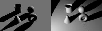
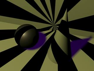
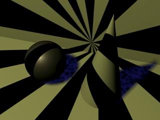
Let's get cracking and develop a wacky light source like that responsible for this picture.
We start by creating an instance of the spot light source:
File -> Create Appearance -> Light -> Spot
Next we provide a connection for the LightColor parameter. Here, we've connected a wave generator function based on the angle in the XY plane to give us our pattern of light and dark. When developing light shaders it's important to use some variation of the SurfacePoint manifold with the Coordinate System parameter set to shader. This ensures that the pattern grows in the space of the light rather than the surface or camera.
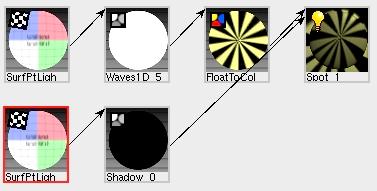
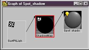
To get shadow effects in our light we connect the Shadow map function into the shadow parameter. In the Shadow function we're provided with controls to cause the generation of a shadow map. We must also connect the Shadow function into a SurfacePoint manifold. And here's an important step. When accessing shadow maps it's important that you use a manifold in a special coordinate system called current. Also we mustn't forget to fill in the shadow map parameter itself.
![]()
And that's how you do it. Now let's say we want textured shadows...
For additional effects, like projected images, refer to the Slide Projector Light example, which also has an example Maya scene.
| Deep shadows are as easy to use as normal shadow maps, but they bring
some powerful new features to the table. One of these features is colored
shadows, which aren't possible with normal shadow maps.
In this example below, we have some sort object with varying kinds of transparency. Its disc shaped leaves are clearly colored and semi-transparent. The body of the object has a procedural functions changing the opacity over the entire surface. Below we see the result of a typical shadow map, it's just
black. |
|
|
|
Setting Up Deep ShadowsGenerating Deep Shadows is as simple as creating a normal shadow map.
Your surface shaders need to be properly set up for Deep Shadows, which means:
Example Maya SceneMaybe the best way to grok what's going on here is to look at the Maya scene file, which has been included for you in the tutorial scene files. You'll find it here: mtor/scenes/transparent_shadows/semitransparent_shadows.ma More Information |
Fake caustic effects can be generated using Deep Shadows. Fake caustics, while not physically correct, are often sufficient to fool most viewers and are often much faster than generating the caustics with photon maps. To create this effect, the objects casting caustics have a different shader applied during the generation of the deep shadow map, using the Adaptor. What follows is the general workflow.
Fake caustics created with Deep Shadows
Setting Up Fake Caustics
Fake caustics were set up in this example this way:
A Maya file of this scene is provided for further examination. It is part of the tutorial scene files. You'll find it here: mtor/scenes/deep_shadows/fake_caustics.ma
Fake Caustics Example #2: Sea Scene
More fake caustics created with deep shadows
In this scene the caustic effect on the ground was created with deep shadows, in the same manner as was used to create the effect in the simpler scene directly above.
A Maya file of this scene is provided for further examination. It is part of the tutorial scene files. You'll find it here: mtor/scenes/deep_shadows/fake_casutic_sea.ma
Here is a simple scene file that uses a Slim shading network to create the effect of a rim light.
Create a Distant Light.
Connect a Facing Foward to the Distant Light's intensity (KI).
Invert the Facing Foward.
Attach the shader to Maya light and render.
A rim light effect.
A Maya file of this scene is provided for further examination. It is part of the tutorial scene files. You'll find it here: mtor/scenes/rim_light/rim_light.ma
You can add reflection effects to directly to surface shaders.
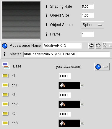
Slim shading networks support all types of reflections and refractions - computing Environment and Reflection Maps, collecting Environment Lights, Ray Tracing and so forth. All of these methods of generating reflections can be built into a shading network through the use of Additive FX shading model.
Additive FX is a uniquely powerful shading model. With it you can add special effects, like reflections, to other shading models. Simply connect a shading model to the Additive FX. Next connect a reflection effect, and that effect will be added to the shading model.
A few uses for Additive FX are Reflection Maps, Environment Maps, and Environment Lights.
Let's work through working with Additive FX . . .
|
|
|
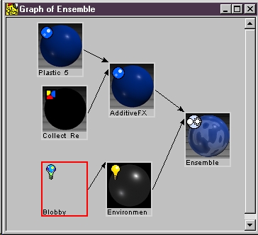
Ensembles & Additive FX An Ensemble along with an Additive FX can visualize certain reflections, like fake environments. Ensembles are special in the way that they can accept connections from multiple shader types, (lights, surfaces, displacements) and put them all together. Here we've connected an Additive FX and an environment light to an ensemble. The Additive FX has a Collect Reflections connected to it. The Ensemble magically displays the reflection of the environment light for your viewing pleasure. Thank you, Additive FX!
|
 |
To get planar reflection maps via Slim.
File->CreateAppearance->Surface->Additive FX
Plug a base shadingmodel into AddtiveFX, here we used Blinn.
Plug an instance of ReflectionMap into the ch1 parameter of AddtiveFX.
Cause the creation of a Reflection map by setting the Frequency parameter of ReflectionMap to Every Frame.
Add a reference to the new reflection map in the Reflection Map parameter of ReflectionMap function: [refmap $OBJNAME].
Attach the AddtiveFX shader to the ground plane and make sure that the ground plane doesn't cast reflections. In Maya there's a per object render stat that controls this.
Et voila!
It's quite easy to add reflection effects to a surface shader and, in fact, we use many of the same steps described above.
Cause the creation of a Reflection map by setting the Frequency parameter of Environment Map to Every Frame.
Add a reference to the new reflection map in the Reflection Map parameter of Environment Map function: [refmap $OBJNAME].
Attach the AddtiveFX shader to an object.
Make sure that the object doesn't cast reflections (we don't want that in the reflection). In Maya there's a per object render stat that controls this.
Environment lights are special lightsource shaders that provide environmental reflections in your scene. Often it's the case that you don't need physically accurate environments. When the reflection effects are secondary, usually it's sufficient (and much cheaper to render) to utilize a single "fake" environment. Most environment light shaders serve exactly this purpose.
You can build any number of environment lights into the shading networks in your scene. Typically, though, a single environment light is sufficent and can be set to affect all "environment-light-aware" shaders in a scene. For a environment light to affect an entire scene, it should be named "world".
To use Environment lights you must first create an environment light:
File -> Create Appearance -> Light -> Environment
For our example we'll simply connect the EnvMap function into the Environment parameter of our new light shader. There we can select a standard lat-long environment map from $RMANTREE/lib/textures/street.env.
Next we must cause one or more surface shaders to actively search for environment lights in the scene. To do this we create an instance of the AdditiveFX shadingmodel:
File -> Create Appearance -> Surface -> AdditiveFX.
There we can wire in a base shading model, say Ceramic, and then connect in an instance of the function Collect Reflections. This is one function that collaborates with external environment lights. Plugging this into the ch1 parameter of AdditiveFX will cause the reflection effects to be added to the base shading model.
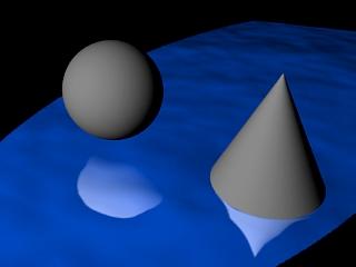
After we attach the AdditiveFX instance to our sphere and cone we must make sure that the environment light shines on these objects. We can do this is a few ways:
Attach the light to all surfaces
Attach the light to a point light source in the scene
Name the light shader "world" causing it to be output by default.
And here's our picture with some reflections.
An adapter allows us to place different shaders on objects under different conditions, depending upon object name, global condition, render pass, etc.
For this example, we'll use an adaptor to create a reflection with falloff. To do this, we'll attach one shader during the reflection pass and then another during the final pass. We'll create a reflection that has a reflection falloff in intensity. The reflection fades the further it is from the surface . . .
A reflection with falloff
In this image, the reflection appears to falloff as the object recedes from the reflecting plane, but all we've done is attach a different shader during the reflection pass. It becomes clearer what's going on when the shader used during the reflection pass is also attached during the final pass . . .
This is the shader used during the reflection pass.
General Workflow
We'll outline the steps to construct this scene.
1) Construct a normal reflection map shader.
2) Create a shader ensemble for the surface of the reflecting object.
3) Create an ensemble adaptor. Switch the controller to "Element Type." Add a new condition and connect the ensemble made in step two.
4) Construct the shader to be applied to the object during the reflection pass. In this example, this shader darkens the basic shader (used for the final pass) using the "Distance" float. It's configured so that the further a surface point is away from the origin, along y, the darker it becomes, creating an appearance of reflection falloff.
5) Add another condition to the adaptor. Connect the new ensemble and enter "reflection" for the condition. This will cause this ensemble to be applied during the reflection pass.
6) Render and tweak.
Example Maya Scene
For further exploration a Maya scene file of the example outlined above is
available (as part of the tutorial
materials).
You'll find it here: ratdocs/rattutorials/mtor/scenes/reflection_falloff/reflection_falloff.ma
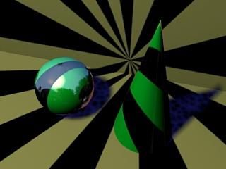
RenderMan supports ray traced reflections, refractions, global illumination and other types of effects. The ray tracing system is straight forward, so ray tracing effects are easy to create, but it also provides interfaces for sophisticated operations.
On this ball special refraction effects were created by filtering the color of the refraction.
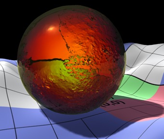
Refractions created with Swiss Army
Setting Up Refractions
In this example refractions were created this way:
Example Maya Scene
For further exploration a Maya scene file of the example outlined above is
available (as part of the tutorial
materials).
You'll find it here: ratdocs/rattutorials/mtor/scenes/rays/refractions.ma
Slim's support for Indirect Illumination allows simple shading networks to create occlusion effects. Occlusion can be used to create subtle shading, by determining how much surfaces are covered by other surfaces. Occlusion can be calculated in a separate pass or built directly into normal shaders (using the layered shader, for instance).
In this example we have a pile of several objects. They have an occlusion shader attached to them. There are no lights in the scene. The coloring is determined by how "near" a surface point is to other surfaces. More samples result in a higher quality image. Less samples have more artifacts but are better for previews.
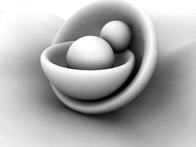
Occlusion created with a simple Slim network
Max Distance "4"
Samples "512"
Max Error "0.1"

Preview quality occlusion
Max Distance "4"
Samples "64"
Max Error "0.5" (which is the default "-1.0")
Setting up an Occlusion Shader
Example Maya Scene
For further exploration a Maya scene file of the example outlined above is
available (as part of the tutorial
materials).
You'll find it here: ratdocs/rattutorials/mtor/scenes/rays/occlusion_shader.mb
Baking Occlusion
Baking occlusion data is an efficient way to reuse indirect illumination data.
Refer to: RAT Tutorial- Baking Occlusion
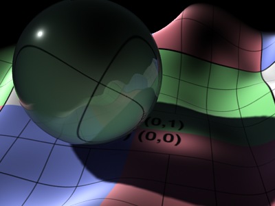
Slim provides the ability to request other data than color when ray tracing. One useful attribute other than color is the length of a ray. We can collect these attributes using Traced Output Variables. In the following trivial (yet tricky) case, the ray length has been used to modulate the opacity of the shader.
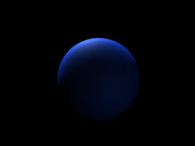
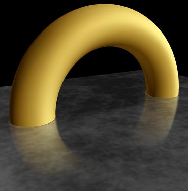
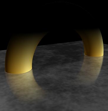
This techniques has been use to create a "jam" shader, which becomes more opaque the further objects recede into it. In the image notice that the yellow tubes disappear into the jelly ball. See image:
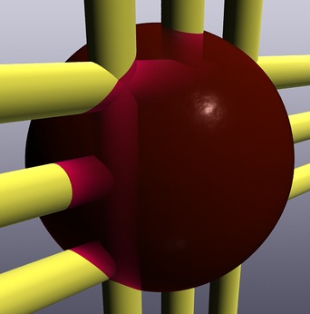
Opacity based on ray length, using Traced Output Variables
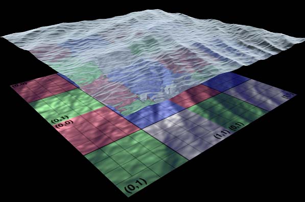
This is a difficult effect to create in other ways, but it's relatively straight forward using ray length. When the ball renders, rays are shot from each point on the surface into the jam from the camera direction. The length of the rays are collected and used to modulate the opacity of the surface at each point. Those rays that are short are black, making the surface transparent. Longer rays are white, which makes the surface more opaque. This makes objects that penetrate the surface of the jelly appear to disappear into it. Here's a diagram that outlines the idea:
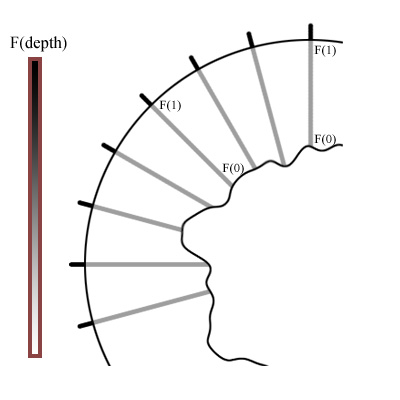
Using traced output variables is an advanced ray tracing technique which allows the creation of many types of effects beyond this simple example.
Setting up Ray Traced Messaging for the Jam Shader
Example Maya Scene
For further exploration a Maya scene file of the example outlined above is
available (as part of the tutorial
materials). You'll find it here: ratdocs/rattutorials/mtor/scenes/rays/jam_shader.ma
|
|
Creating a fog shading network
1. Create a volume fog node.
2. Add a ramp to the fog's color parameter, and color it.
3. Connect a planar Z projection to the ramp's manifold.
4. Connect a surface point to the projection and use "NDC" as shader
space to apply the projection in normalized raster space.
5. Name the fog "world" as this special
case name will apply the fog to the entire scene.
Now the volume fog is ready to render. You'll find that volume fog is costly to render, but it can be a useful, if expensive, solution.
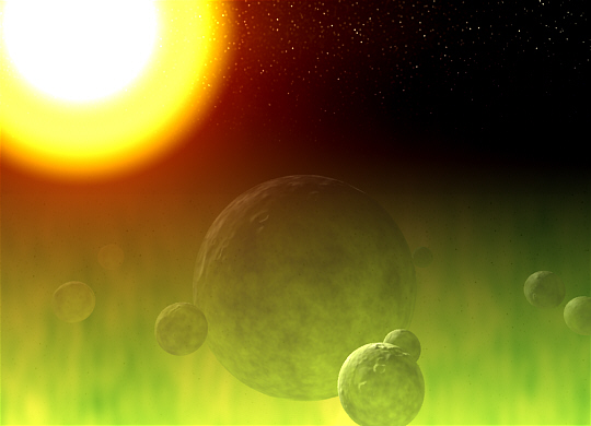
This basic scene was created using Slim's volume fog, without the using raytracing. Deep shadows were used to achieve the colored fog effect. Note that the opacity of the object must be colored to get the correct effect, correctly.
Creating colored fog:
Create volumetric fog with MTOR.
Create a spot light and attach a Slim spot light shader with a shadow map.
Enable Deep Shadows in the spot light shader's shadow map.
The shadow map's Volume Interpretation parameter should be switched from "Discreet" to "Continuous."
Point the light at a semi-transparent object.
The semi-transparent object's opacity (not the surface) must be colored.
The opacity's color must be inverted.
Render.
Volumetric effects are computationally expensive. Handle with care.
Colored fog created with deep shadows
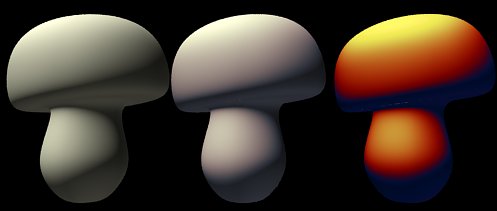
Sophisticated effects can be created by mapping ramps to the diffuse and specular elements of an objects. These effects range from adding subtle color warmth to fake iridescence.
Adding Color Warmth to Kd
In the image below there are three mushrooms. The first mushroom has a plain
"clay" shader attached to it. The second mushroom has a color ramp
mapped to its diffuse value, which creates a much more interesting look. It's a
rather subtle effect, but it does adds a perceptible "warmth" and
character to the object, making it a little less "CG-like." In the
third mushroom the color mapping is heavily saturated to more clearly show what
is going on here.
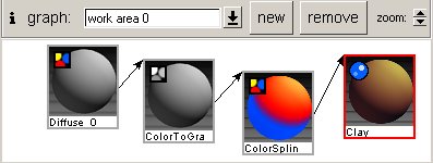
Here's the graph of the shader used to map the diffuse values.
It's quite simple.
1. Create a shading model (in this case a clay).
2. Connect a Color Spline
to the shading model's color parameter.
3. Connect a ColorToGray
to the Color Spline.
4. Connect a Diffuse
node to the Color To Gray.
5. Tweak and Render.
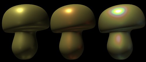
Adding Color Warmth to Specularity
In the example below color ramps are mapped to the specularity of the objects. A
plain shader has been attached to the first object, with no color mapping, just
straight speculartiy. In the second mushroom, a ramp has been mapped to the
specularity creating a more interesting effect, where the specular highlight
turns red as it falls away from the center. Again this adds more character to
the object. With the third mushroom we've created fake iridescence by mapping a
color spectrum to the specular channel.
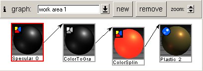
Mapping Ramps to specularity is straightforward
1. First a plastic shading model was created.
2. Next a Color Spline
connected to the plastic's "Specular Color" parameter.
3. A ColorToGray
was then connected to the color spline.
4. A Specular node
was then connected to the Color To Gray.
5. The Color Spline's ramp was the edited as desired.
Here's the graph of the shader . . .
|
Take our gray torus here. We're going to add a glass shader to it. Actually, we'll create three different shaders that are both transparent and shiny at the same time. The first is very simple, and the second and third become a little more complex. So here we go . . . |
|
1) Basic Glass To add a specular highlight to a transparent shading model all we need is to create an Additive FX.
That's all. Now the Additive FX combines the specular with the plastic, creating a shiny transparent surface, like glass. This is pretty basic. Here's the graph . . .
|
 |
|
2) Fancier Glass Continuing to work with the same shader, we'll add a little more character to the glass, by modulating the opacity of the surface. When we look at transparent objects in the real world, like glass, we notice that the material becomes more opaque at the edges. This is something we can emulate with a Facing Forward float.
We can see in the image that the object has a little more "substance" now, while still looking transparent. Here's the graph . . . |
 |
|
3) Fancy Glass Now we'll add a fake reflection to the object. We'll do this by attaching an environment light to the object.
Now this is a reasonably complex glass shader. There's still a lot of room for improvement, however, but it's important to pick shaders with the right amount of complexity. Many times the basic glass is an ample solution. No reason to go overboard, unless necessary. This shader could be improved with refraction effects, either by faking refractions (not perfect, occasionally useful) with EnvironmentMapPlus or by through the use of a ray server using TraceRefractions. Here's the graph of the shader . . . |
 |
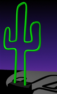
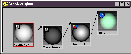
It's possible to create a shader that simulates glows effects. This particular glow effect is not really a glow, only an imitation, being based entirely upon a specially created surface shader (that utilizes Facing Forward float, returning a value depending on how a surface faces the camera). This glow effect can be passable in many cases and is relatively cheap to render. Here is a heavy-handed example of the glow effect . . .
 |
 |
 |
|
1) A neon cactus with incandescence. |
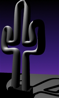
2) The outer geometry is added and ready for glow shader. |
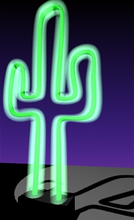
3) Neon cactus with |
 |
|
1) The shading model is a Blinn with a glowing
incandescence. |
1) Create glow shader. (See diagram above.) The key is to plug a Facing Forward float into shader opacity.
2) Create the glow geometry. Select the geometry that will be glowing, duplicate it, and resize it to envelop the original geometry, as the large cactus shell in figure #2.
3) Attach the glow and render and tweak.
Here's an example Maya scene file which demonstrates the use of both a TCL
box and a RIB box, and then in combination.
Example Maya Scene
For further exploration a Maya scene file of the example outlined above is
available (as part of the tutorial
materials). You'll find it here: ratdocs/rattutorials/mtor/scenes/tcl_box/tclprocs.ma
It's probably easiest to look at the RIB box first. It makes about 5 different
kind of attribute based calls. Some of them don't require the TCL box, but the
last couple, which refer to a TCL variable and a TCL proc do. In one example the
TCL proc appends a directory like set of chars to the standard Maya
stringAttribute.
Note: This is set in the RenderMan Globals to pop up "nedit" as the
renderer, just to see if the stuff made it in to the RIB. If nedit isn't on
your machine, set up the custom renderer in the Render Globals Custom
Tab to be your favorite editor, like notepad.
|
Pixar
Animation Studios |
 Creating
the effect of glass, or any shiny transparent object, can be a little
tricky with Slim. It's not necessarily difficult, but take a look at a
typical surface model, like Plastic. It seems shiny enough, a good
candidate for glass, but as its opacity is reduced, its specularity is
reduced right along with it. This means when the Plastic shading model
is transparent like glass, it has no shininess, and simply won't cut the
mustard.
Creating
the effect of glass, or any shiny transparent object, can be a little
tricky with Slim. It's not necessarily difficult, but take a look at a
typical surface model, like Plastic. It seems shiny enough, a good
candidate for glass, but as its opacity is reduced, its specularity is
reduced right along with it. This means when the Plastic shading model
is transparent like glass, it has no shininess, and simply won't cut the
mustard.